- 您现在的位置:买卖IC网 > Sheet目录1214 > EVAL-ADE7878EBZ (Analog Devices Inc)BOARD EVAL FOR ADE7878
�� �
�
�APNOLOAD� =�
�� NOLOAD� � PMAX�
�V� n� I�
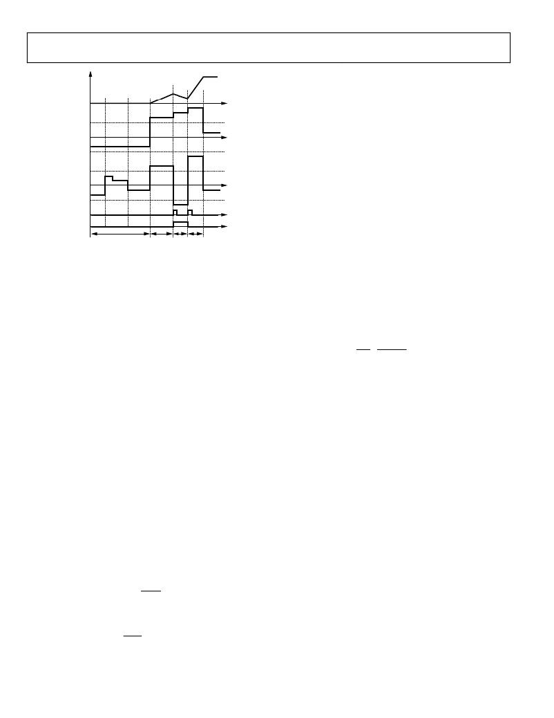
�ADE7854/ADE7858/ADE7868/ADE7878�
�REACTIVE�
�ENERGY�
�NO-LOAD�
�THRESHOLD�
�REACTIVE�
�POWER�
�NO-LOAD�
�THRESHOLD�
�NO-LOAD�
�THRESHOLD�
�ACTIVE�
�POWER�
�REVRPx� BIT�
�IN� STATUS0�
�xVARSIGN� BIT�
�IN� PHSIGN�
�VARNOLOAD� POS� NEG� POS�
�SIGN� =� POSITIVE�
�Figure� 81.� Reactive� Power� Accumulation� in� Sign� Adjusted� Mode�
�Sign� of� Sum-of-Phase� Powers� in� the� CFx� Datapath�
�The� ADE7854� /� ADE7858� /� ADE7868� /� ADE7878� have� sign�
�detection� circuitry� for� the� sum� of� phase� powers� that� are� used� in�
�the� CFx� datapath.� As� seen� in� the� beginning� of� the� Energy-to-�
�Frequency� Conversion� section,� the� energy� accumulation� in� the�
�CFx� datapath� is� executed� in� two� stages.� Every� time� a� sign� change� is�
�detected� in� the� energy� accumulation� at� the� end� of� the� first� stage,�
�that� is,� after� the� energy� accumulated� into� the� accumulator�
�reaches� one� of� the� WTHR,� VARTHR,� or� VATHR� thresholds,� a�
�dedicated� interrupt� can� be� triggered� synchronously� with� the�
�corresponding� CFx� pulse.� The� sign� of� each� sum� can� be� read� in�
�the� PHSIGN� register.�
�Bit� 18,� Bit� 13,� and� Bit� 9� (REVPSUM3,� REVPSUM2,� and�
�REVPSUM1,� respectively)� of� the� STATUS0� register� are� set�
�to� 1� when� a� sign� change� of� the� sum� of� powers� in� CF3,� CF2,�
�or� CF1� datapaths� occurs.� To� correlate� these� events� with� the�
�pulses� generated� at� the� CFx� pins,� after� a� sign� change� occurs,�
�Bit� REVPSUM3,� Bit� REVPSUM2,� and� Bit� REVPSUM1� are� set�
�in� the� same� moment� in� which� a� high-to-low� transition� at� the�
�CF3,� CF2,� and� CF1� pin,� respectively,� occurs.�
�Bit� 8,� Bit� 7,� and� Bit� 3� (SUM3SIGN,� SUM2SIGN,� and� SUM1SIGN,�
�respectively)� of� the� PHSIGN� register� are� set� in� the� same� moment�
�with� Bit� REVPSUM3,� Bit� REVPSUM2,� and� Bit� REVPSUM1� and�
�indicate� the� sign� of� the� sum� of� phase� powers.� When� cleared� to�
�0,� the� sum� is� positive.� When� set� to� 1,� the� sum� is� negative.�
�Interrupts� attached� to� Bit� 18,� Bit� 13,� and� Bit� 9� (REVPSUM3,�
�REVPSUM2,� and� REVPSUM1,� respectively)� in� the� STATUS0�
�register� are� enabled� by� setting� Bit� 18,� Bit� 13,� and� Bit� 9� in� the�
�MASK0� register.� If� enabled,� the� IRQ0� pin� is� set� low,� and� the�
�status� bit� is� set� to� 1� whenever� a� change� of� sign� occurs.� To� find�
�the� phase� that� triggered� the� interrupt,� the� PHSIGN� register� is�
�read� immediately� after� reading� the� STATUS0� register.� Next,� the�
�status� bit� is� cleared,� and� the� IRQ0� pin� is� set� high� again� by� writing�
�to� the� STATUS0� register� with� the� corresponding� bit� set� to� 1.�
�Data� Sheet�
�NO� LOAD� CONDITION�
�The� no� load� condition� is� defined� in� metering� equipment� standards�
�as� occurring� when� the� voltage� is� applied� to� the� meter� and� no� cur-�
�rent� flows� in� the� current� circuit.� To� eliminate� any� creep� effects� in�
�the� meter,� the� ADE7854� /� ADE7858� /� ADE7868� /� ADE7878� contain�
�three� separate� no� load� detection� circuits:� one� related� to� the� total�
��only),� one� related� to� the� fundamental� active� and� reactive� powers�
��No� Load� Detection� Based� On� Total� Active,� Reactive�
�Powers�
�This� no� load� condition� is� triggered� when� the� absolute� values� of�
�both� phase� total� active� and� reactive� powers� are� less� than� or� equal�
�to� positive� thresholds� indicated� in� the� respective� APNOLOAD�
�and� VARNOLOAD� signed� 24-bit� registers.� In� this� case,� the� total�
�active� and� reactive� energies� of� that� phase� are� not� accumulated�
�and� no� CFx� pulses� are� generated� based� on� these� energies.� The�
�APNOLOAD� register� represents� the� positive� no� load� level� of�
�active� power� relative� to� PMAX,� the� maximum� active� power�
�obtained� when� full-scale� voltages� and� currents� are� provided� at�
�ADC� inputs.� The� VARNOLOAD� register� represents� the� positive�
�no� load� level� of� reactive� power� relative� to� PMAX.� The� expres-�
�sion� used� to� compute� APNOLOAD� signed� 24-bit� value� is�
�(47)�
�V� FS� I� FS�
�where:�
�PMAX� =� 33,516,139� =� 0x1FF6A6B,� the� instantaneous� power�
�computed� when� the� ADC� inputs� are� at� full� scale.�
�V� FS� ,� I� FS� are� the� rms� values� of� phase� voltages� and� currents� when�
�the� ADC� inputs� are� at� full� scale.�
�V� n� is� the� nominal� rms� value� of� phase� voltage.�
�I� NOLOAD� is� the� minimum� rms� value� of� phase� current� the� meter�
�starts� measuring.�
�The� VARNOLOAD� register� usually� contains� the� same� value� as�
�the� APNOLOAD� register.� When� APNOLOAD� and� VARNOLOAD�
�are� set� to� negative� values,� the� no� load� detection� circuit� is� disabled.�
�Note� that� the� ADE7854� measures� only� the� total� active� powers.�
�To� ensure� good� functionality� of� the� ADE7854� no-load� circuit,�
�set� the� VARNOLOAD� register� at� 0x800000.�
��section,� the� serial� ports� of� the� ADE78xx� work� on� 32-,� 16-,� or�
�8-bit� words� and� the� DSP� works� on� 28� bits.� APNOLOAD� and�
�VARNOLOAD� 24-bit� signed� registers� are� accessed� as� 32-bit�
�registers� with� the� four� MSBs� padded� with� 0s� and� sign� extended�
�to� 28� bits.� See� Figure� 35� for� details.�
�Bit� 0� (NLOAD)� in� the� STATUS1� register� is� set� when� this� no�
�load� condition� in� one� of� the� three� phases� is� triggered.� Bits[2:0]�
�(NLPHASE[2:0])� in� the� PHNOLOAD� register� indicate� the� state�
�of� all� phases� relative� to� a� no� load� condition� and� are� set� simulta-�
�neously� with� Bit� NLOAD� in� the� STATUS1� register.� NLPHASE[0]�
�indicates� the� state� of� Phase� A,� NLPHASE[1]� indicates� the� state�
�Rev.� H� |� Page� 64� of� 100�
�发布紧急采购,3分钟左右您将得到回复。
相关PDF资料
EVAL-ADE7880EBZ
BOARD EVAL FOR ADE7880
EVAL-ADE7953EBZ
BOARD EVAL FOR ADE7953
EVAL-ADF4002EBZ1
BOARD EVAL FOR ADF4002
EVAL-ADG788EBZ
BOARD EVALUATION FOR ADG788
EVAL-ADM1021AEB
BOARD EVAL FOR ADM1021
EVAL-ADM1023EB
BOARD EVAL FOR ADM1023
EVAL-ADM1031EB
BOARD EVAL FOR ADM1031
EVAL-ADM1062TQEBZ
BOARD EVALUATION FOR ADM1062TQ
相关代理商/技术参数
EVAL-ADE7880EBZ
功能描述:BOARD EVAL FOR ADE7880 RoHS:是 类别:编程器,开发系统 >> 评估演示板和套件 系列:* 产品培训模块:Obsolescence Mitigation Program 标准包装:1 系列:- 主要目的:电源管理,电池充电器 嵌入式:否 已用 IC / 零件:MAX8903A 主要属性:1 芯锂离子电池 次要属性:状态 LED 已供物品:板
EVAL-ADE7880EBZ
制造商:Analog Devices 功能描述:ADE7880, ENERGY METER, 3 PH, SPI, I2C, E
EVAL-ADE7913EBZ
制造商:AD 制造商全称:Analog Devices 功能描述:3-Channel, Isolated, Sigma-Delta ADC with SPI
EVAL-ADE7953EBZ
功能描述:BOARD EVAL FOR ADE7953 RoHS:是 类别:编程器,开发系统 >> 评估演示板和套件 系列:- 标准包装:1 系列:PSoC® 主要目的:电源管理,热管理 嵌入式:- 已用 IC / 零件:- 主要属性:- 次要属性:- 已供物品:板,CD,电源
EVAL-ADF4001EBZ2
制造商:Analog Devices 功能描述:Evaluation Board For Pll Frequency Synthesizer 制造商:Analog Devices 功能描述:ADF4001 PLL SYNTHESIZER EVAL BOARD
EVAL-ADF4002EB1
制造商:Analog Devices 功能描述:EVAL BOARD - Bulk
EVAL-ADF4002EBZ1
功能描述:BOARD EVAL FOR ADF4002 RoHS:是 类别:编程器,开发系统 >> 评估演示板和套件 系列:- 产品培训模块:Obsolescence Mitigation Program 标准包装:1 系列:- 主要目的:电源管理,电池充电器 嵌入式:否 已用 IC / 零件:MAX8903A 主要属性:1 芯锂离子电池 次要属性:状态 LED 已供物品:板
EVAL-ADF4007EBZ1
功能描述:BOARD EVALUATION FOR ADF4007EB1 RoHS:是 类别:编程器,开发系统 >> 评估演示板和套件 系列:- 标准包装:1 系列:PSoC® 主要目的:电源管理,热管理 嵌入式:- 已用 IC / 零件:- 主要属性:- 次要属性:- 已供物品:板,CD,电源